Overview of Nuke
This week an overview of Nuke where introduced, the basics of the viewer window, time line including in and out points, the projects settings information’s in the viewer (Bottom), Gama and Gain control de exposure of the image (top viewer). Also, showing the Node Graphs and adding more nodes to the project.
Setting project directory
Each section, the projects will be at the desktop. A folder called Nuke_Overview where downloaded from blackboard to the desktop.
Now with my Nuke 13.0v1 open and before bring any Nuke Comp script, Press S in the Keyboard to set up the project settings. Pressing the `Script Directory` folder in project settings box and search to Nuke_Overview folder saved to the desktop and press open not going in to any of the folders. With the project directory set which is very similar to Maya, to have it all in specific folders, to be a where when to move files around, and then, go to Files, Insert Comp Nodes, navigates to the Nuke_Overview folder saved to the desktop once again, click in the nuke_scripts, and choose the folder, and click open.
To view the image on the viewer window click and press 1 in the keyboard.
Rodrigo Rodrigues
Week 1: Rigging Overview - Tentacle
Jason Martine
Overview
This week the lesson was to create a Model (basic tentacle), create a joint Chain, Skin mesh to joints, and add controls to the joints. At the end of the lesson a broad understanding of a basic workflow in how to create rig using Maya Software.
Modeling the tentacle (basic)
1.

2. Select the top Vertex then press B for soft selection, holding down B choose the size of the soft selection using right mouse.

3. then scaling the Z and the X

4.

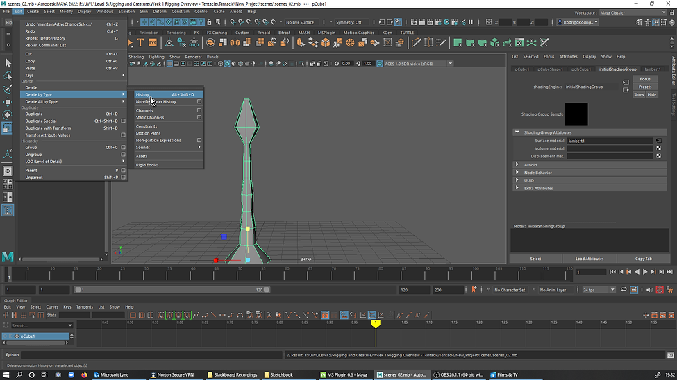
5. Delete History After finishing the modeling. Edit, Delete by type and click History or Alt+Shift+D .
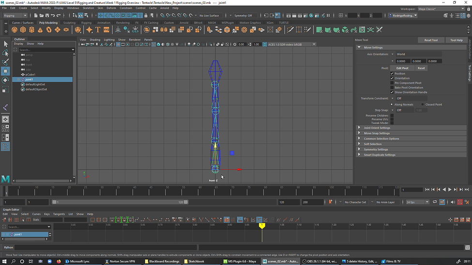
6. Adding the Skeleton, hold down X to aline with the Grid
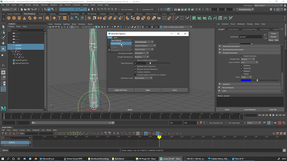
7.Bind the skin. Selecting the Root Joint + Shift +selecting the Joint and then Skin, bind skin, reset and apply

7a.
8. Creating NurbsCircle... First Nurb Radius of 3 and then duplicating a second and third Nurbs scaling down the radius of it.

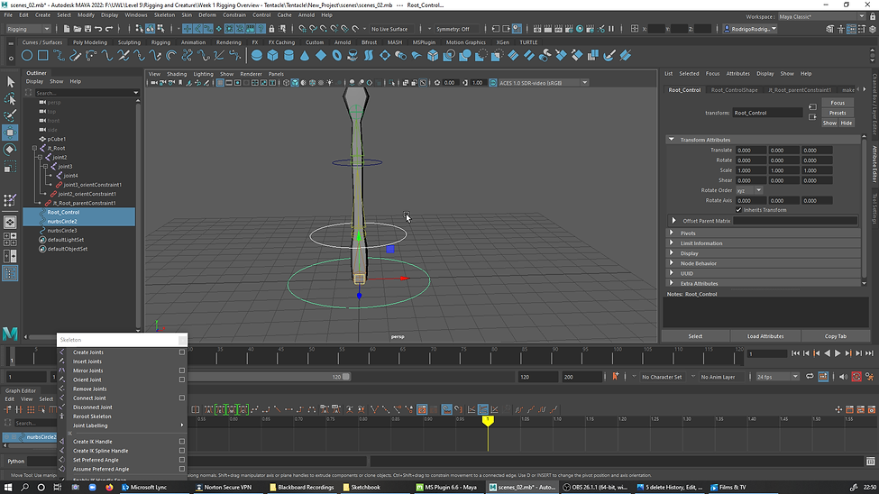
9. With the Translated Move tool control selected, select the Nubs circle to hold down Keyboard V +Meddle Mouse select with a slice movement in the joints snapin the circle up to the place.

10 Modify and freeze transform to zero down the valius in attributes

11. Linking the Rotation of the Nurbs with the rotation of the joints. Clicking in the Nurbs Root then Shift +Root Jt_root following the process like the picture
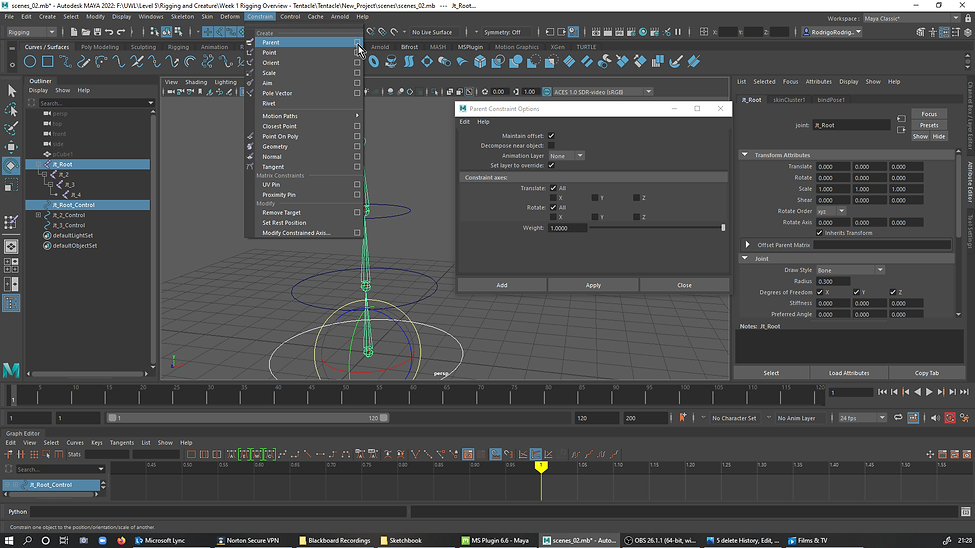
12. Same process for the Joints but on Orient and not Parenting as the previous Rood Circle. Parenting(translations), Orient(Rotations)

12a.

13. Parenting the controls - meddle to the root
13a. Parenting the controls - Top to the meddle.

13a. Parenting the controls - Top to the meddle.
14. Parenting the controls done.
15. Expression Editor - Copied the SelectedObjectAttribute to the Expression box and then added = sin(time*6)*60;
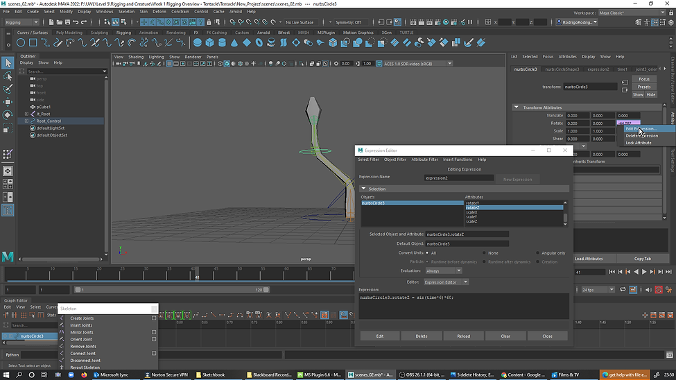
15a. 15b.
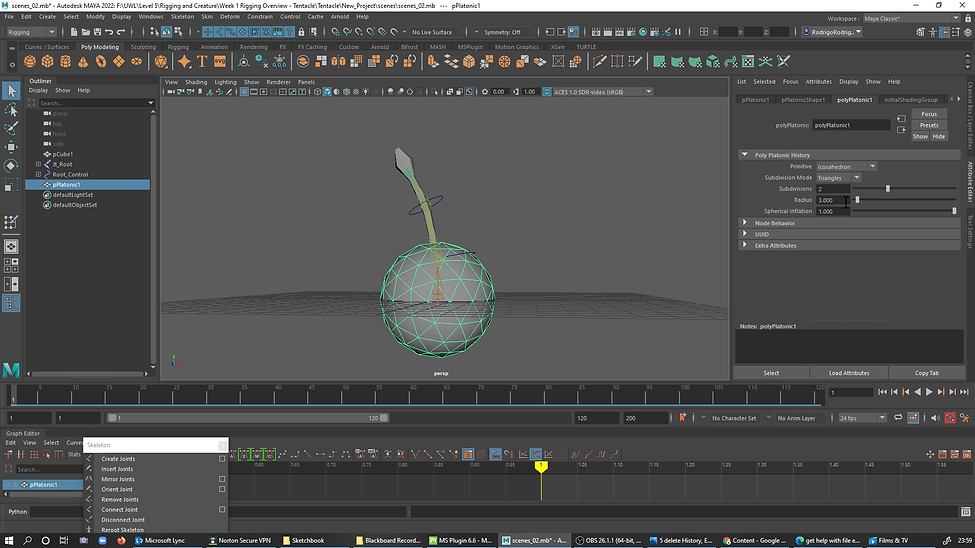
16. Adding a platonic solid to make the tentacle object. SubdivisionMode to Triangles and...

16a. ...subdivisions 2 and Radious 3.000.
17. Tentacle Mash objects fixing when is off.
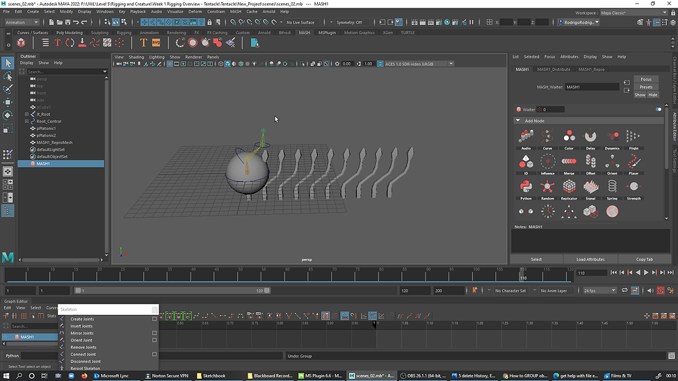
17a. Tentacle Mash objects fixing when is off - Selecting Tentacle and then Group it (Ctrl+G). Go to Mash And click CreateMash Network.

17b. Tentacle Mash objects fixed.

18. Turning off the CachPlayBack, allows the Mash to work properly. 15b.
19.

20. Attaching the Tentacles Mash to the surface of the sphere. MASH connecting dragging with the meddle mouse to the ImputMesh
21. Created a Camera on the Grid.

22. In Panels, perspective Camera1 view set.

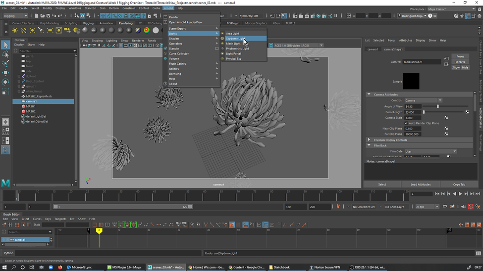
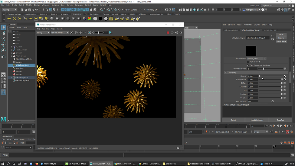
23. In Arnoud, Light, Skydome Light added
24. In AttribuiteEditor-aiSkyDomeLightShap1-SkyDomeLight Attributes- Exposure set to (-4000) and Samples to (2).24. in AttribuiteEditor-aiSkyDomeLightShap1-SkyDomeLight Attributes- Exposure set to (-4000) and Samples to (2)

25. Render Settings-Presets.- Import render Settings then click Default Settings
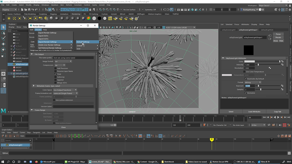
25a. In render Settings also checked the Tab Arnold Render and then just close the Render Settings box.

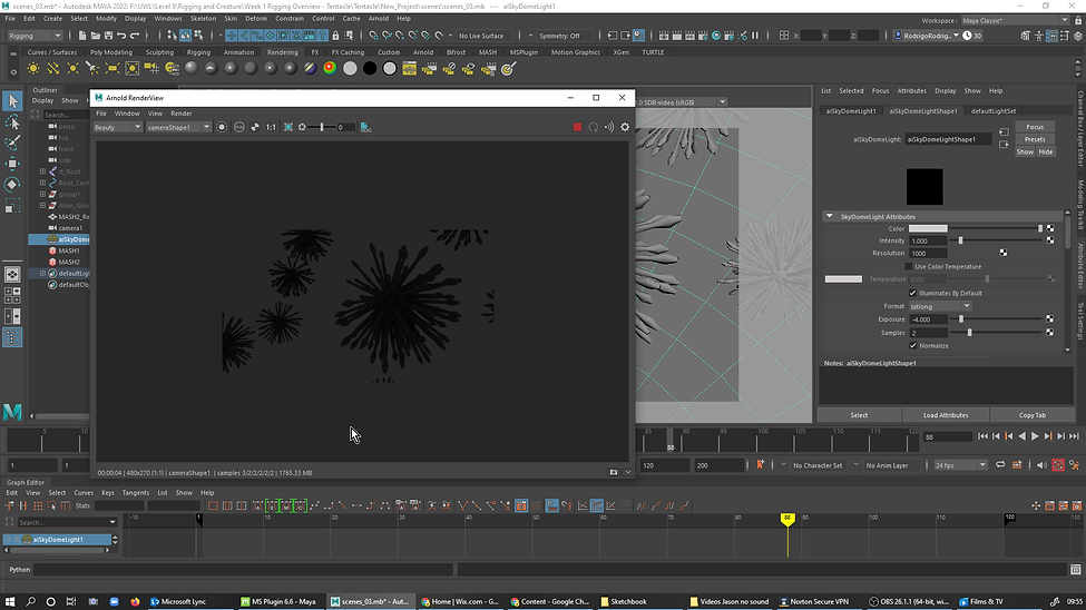
26. Opened the ArnoldRenderView, on the tab View, TestResolution was set to 50%.
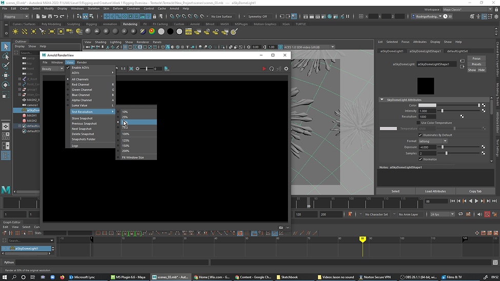
26a.
27. SpotLight Added, in Panels
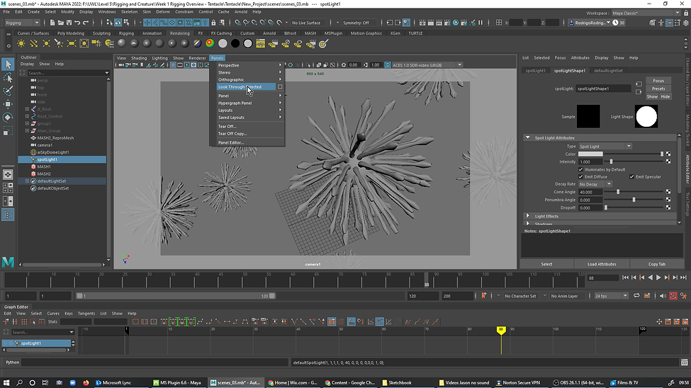
27a.

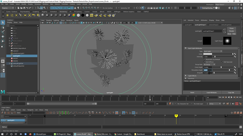
27b. Turned the scene around and Changed the Cone Angle to cover the entire scene.

27c. Also added valiuns to the Penumbra Angle and Dropoff.
27d. Just below of the last step in Arnoud it was added 15.000 to exposure and Samples (2)

27e. Selected back to camera viewing Panels and then it was added more value in the exposure of the SpotLightShape1 at the Attributes Editor

28. Mash selected, in Attribute Editor-Mash2_ReproMeshShape-Arnold-Subdivision it was changed Type to Catclark and Interaction to (3)

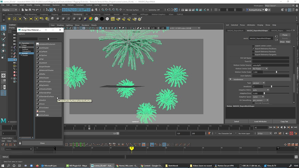
29. AssignNewMaterial-Arnold-aiStandartSurface.
30. In Subsurface it was added (0.961) to Weight, type changed to RandomWalk.
%20to%20Weight%2C%20type%20changed%20to%20randomwalk.png)
31.

31a.

31b.

32.

32a.

33. Skydome Visibility camera set to 0.
34. Render settings, it was added (4) to ArnoldRender in Camera AA and (3) to SSS .
%20to%20ArnoldRender%20in%20Camera%20AA%20and%20(3)%20to%20SSS%20.png)
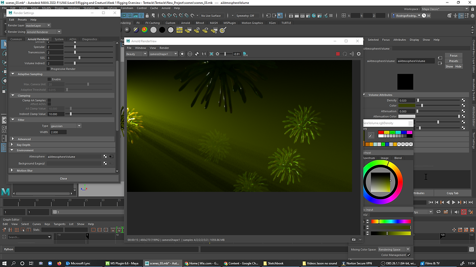
35.Click in aiAtnosphereVolumeVolume in RenderSettings.

35a. Density to 0.200 and color light blue.

35b. Change exposure down to 15.872 at the attributes of the SpotLight.

35c.Back to aiAtmosphereVolume and changed the Density to 0.020.
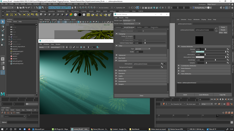
35d... and colors...

35e. ..playing around with the colors...
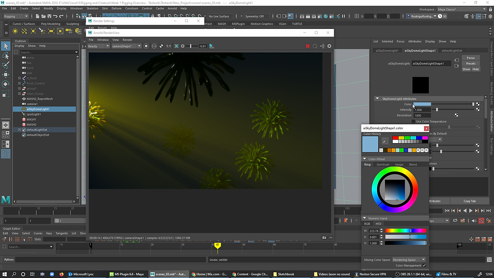
36. skydome camera visibility set to 1.000.

37. SkyDome Color changed...
38. AiAtmosphereVolume Density to 0.040.

Lesson week 1 basic tentacle modeling, creating a joint Chain, Skin mesh to joints, and adding controls to the joints.
Final result - Vegan Virus
Week 2: Joint Creation - ROBOT
Jason Martine
Overview
This week the lesson was to make our own Joints in Maya, to the robot below..
Rigging Lesson
1.

Week 3: SKINNING - ARM
Jason Martine
Overview
Lesson general notes :
This week we overlooked to PaintSkinweightsToll
B Scale Brush
N Intensity
Shift Smooth
Ctrl Paint reverse
In Select
Windows/General editors/content Browser - To get obj and creatures etc
Discord.com
After the anime action the joints fo to Rigging mode, Skin, bind skin and apply and close
Right-click in the Mesh select the paint mode
LocK the entire Joints
SelectMode using the tool settings box of the PaintSkinweightsToll, in vertices select the entire arm with the shoulders open
Add light and rendering
Spotlight
Ps In render settings do the atmosphere ... after applying it right-click in the name and break the connection
Cartoon rendering and tonemap...
1. Jt_ROOT selected and Shift select the Arm, go to SKIN-BindSin, click in the Box to acces BinSkinOptions, click in Edit, ResetSettings and then BindSkin to apply.
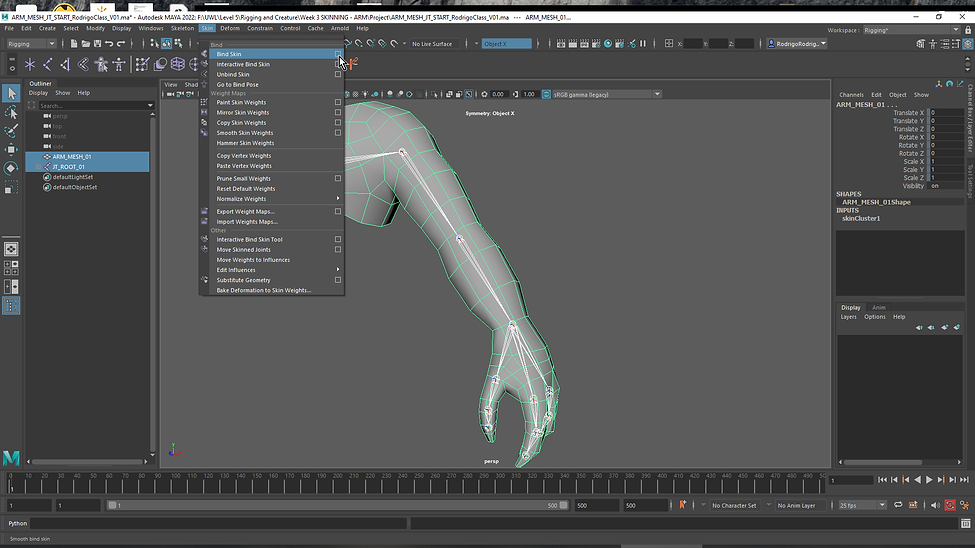
1a. The arm should be attached to the Joints to be able to animate it.
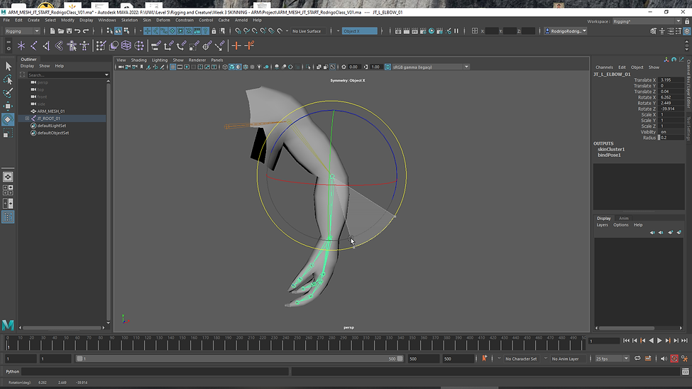
2. Animated arm and fingers. Here is a exemple how to close hands animated

3. Select, Grow, then, Press G to Grow to expand the selection of the Vertices.

4. Workflow using Modify and Shrink to paintTool the fingers.
4a.
5. Using Smooth Paint Operation.
6. Selecting, PaintMode, In PaintOperation Replace, check Value, and then Flood.
Final.
Week 4: Rigging Controls Robot - MKII PT 01
Jason Martine
1. Adding mocap data to the robot.
assignment 1
Jason Martine
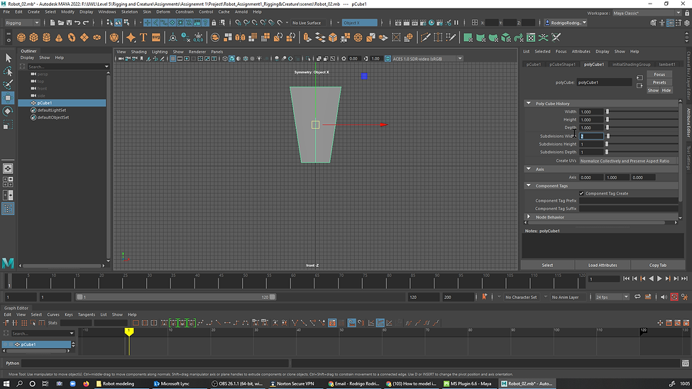
2. started with a Cube subdevied widht (2).
_%20.png)
3. Face selected, deleted the left side

3a.

4.DuplicateSpecial

5. ResetSetings

6. Selected Intance and change the ScaleX to -1 duplicateSpecial, duplicating it to the left side.
7. Shift+RBC, InsertEdgeLoopTools

8. Scaled the added looped edges

9. Create, curveTools, CVCurveTools to create a curve line in the RightUperBody of the Robot

10. Snaped to Grids. To center the curve.

11. Create, NURBS Primitives, Circle

11a. Positioned the Nurbs at the center of the curve, RotateZ to 90.

12a. Select the Nurbs and the Curve and then in Surfaces click Extrude.
12b. Edit, DelteByType, History, to unconnect the curve and Nurbes from the object, so it can be deleted
13. Edge mode, selected and adge, ToolSettings , Mesh, selected Connect to create more edges
13a.Shaping the robt in Vertices Mode

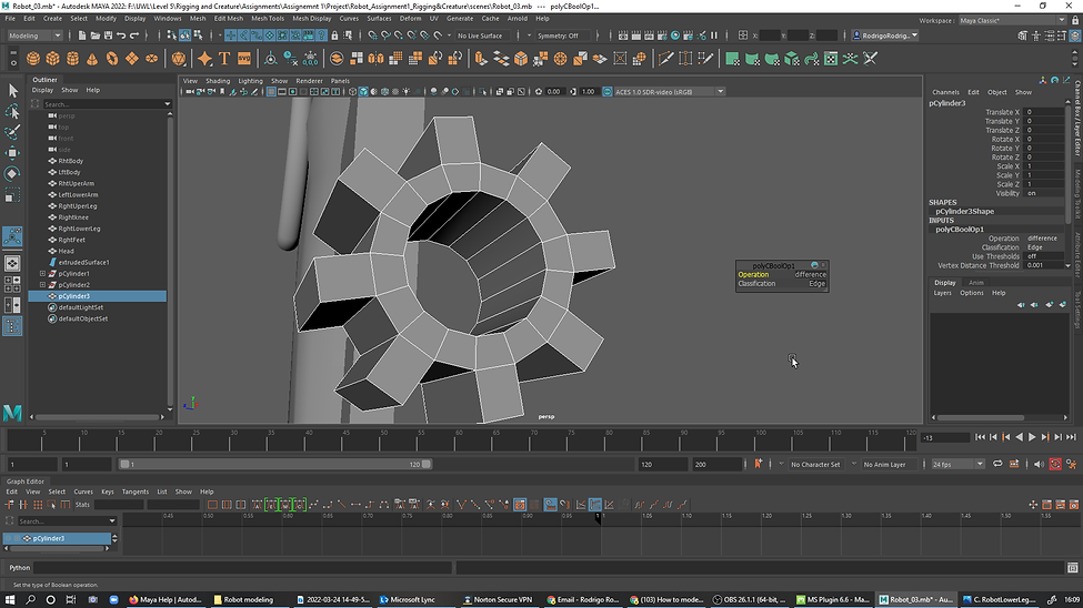
14. Cylinder, subdivided by 16, celected faces and extruded. A second Cylinder placed inside the mecanism, then Meshi, BuBulians and then Diference.
A. Centimeters set to work with the real world mesurments..
b
C
D
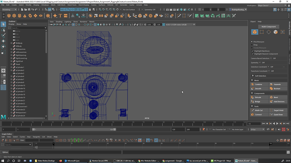


Rigging


Final
WEEK 9 BLENDSHAPES
Jason Martine
BLENDSHAPE INTRO
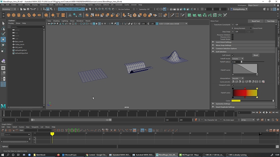
BLENDSHAPES COMBINATION TARGET


BLENDSHAPES CONTROLS POSE EDITOR


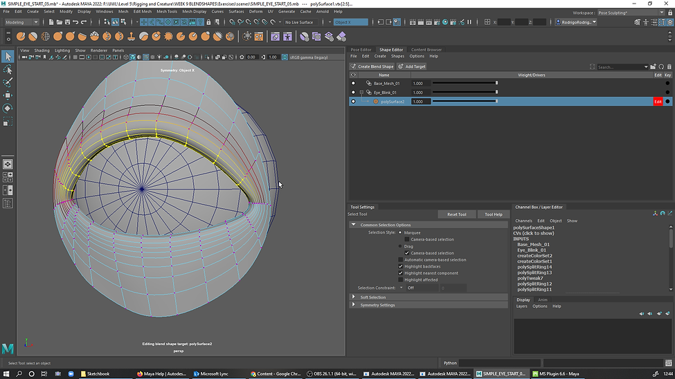
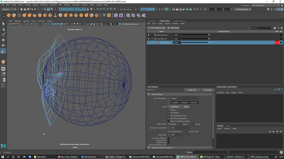
BLENDSHAPES EYE LID


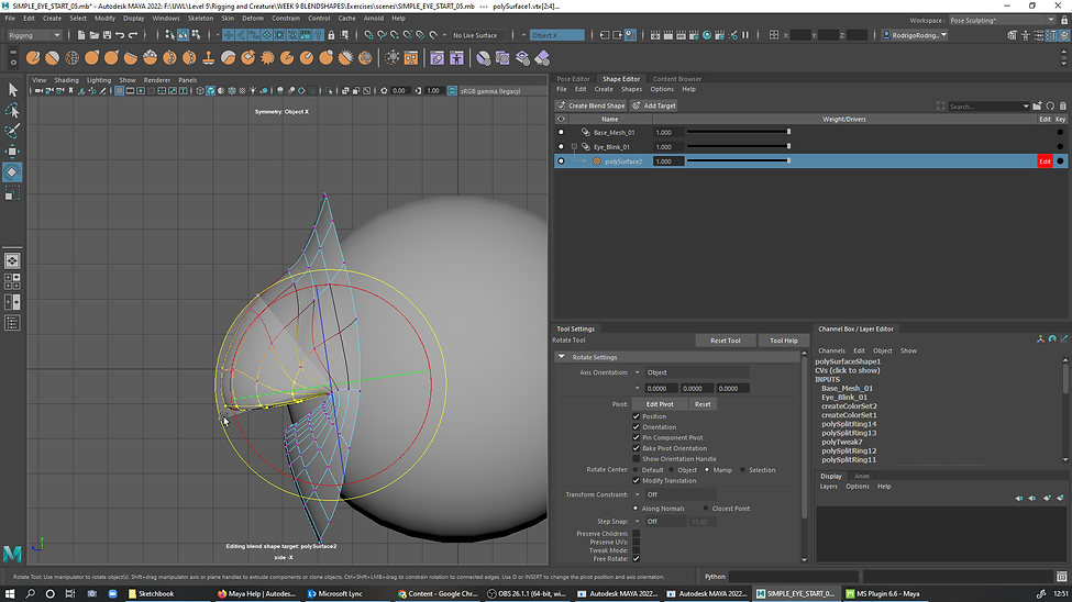


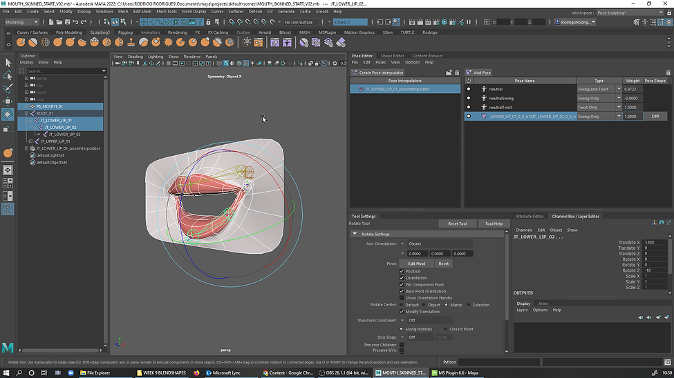
BLENDSHAPES POSE EDITOR

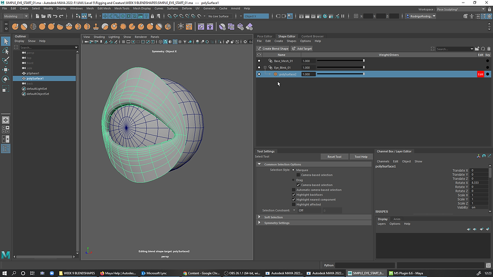
BLENDSHAPES SHAPE EDITOR INTRO

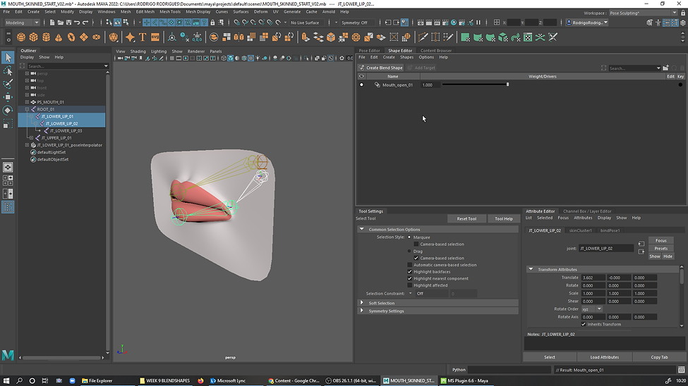
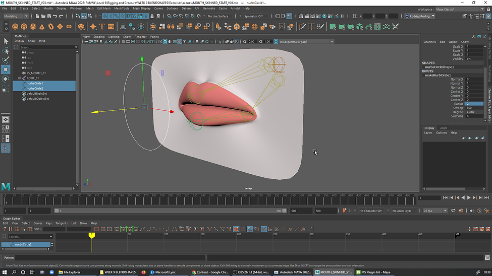
MOUTH RIG CONTROLLERS
assignment 2
Jason Martine